I. Key Parameter Selection for High-Current Switch Contacts
(I) Criteria for Selecting Contact Diameter
In the field of high-current switches, due to the relatively large structural errors, large silver-surface contacts are often required to compensate for these deficiencies. Based on practical application experience, generally speaking, when the rated current of the switch is within 10A, a contact with a diameter of 3mm is suitable; when the current range is between 10 - 20A, a contact with a diameter of 3.5 - 4mm is more appropriate. The specific details are shown in the following table:
| Rated Current Range of the Switch | Suitable Contact Diameter |
| Within 10A | 3mm |
| 10 - 20A | 3.5 - 4mm |
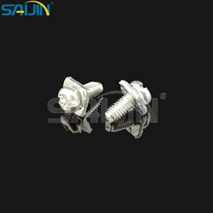
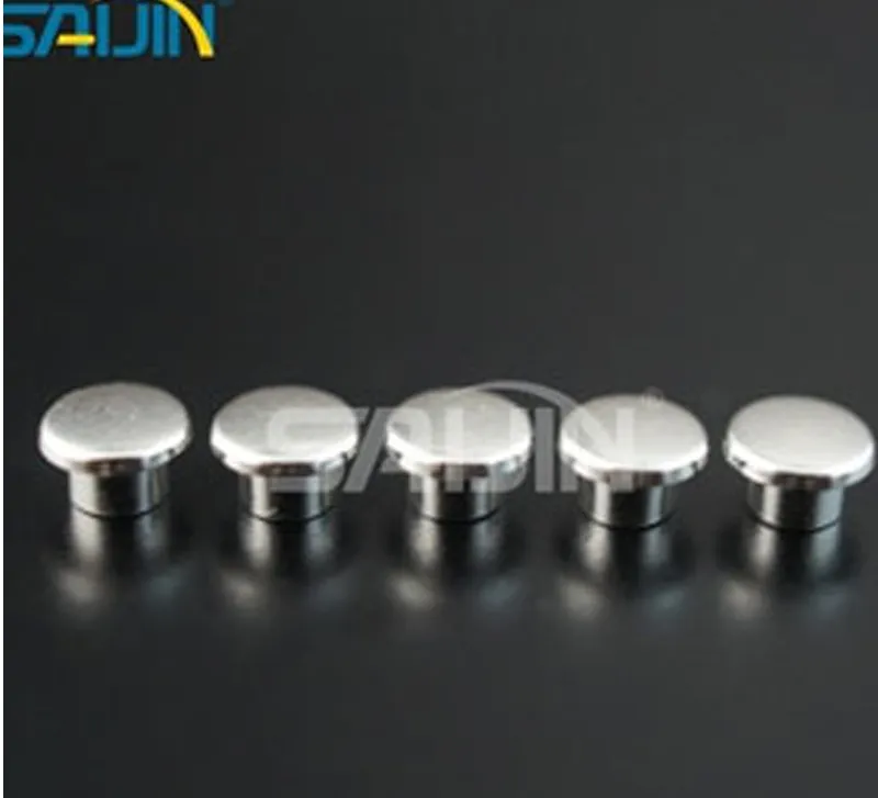
(II) Considerations for the Arc of the Contact Surface and the Small r Angle
Theoretically, the static contact of the switch is in a planar shape, and the moving contact is in an arc shape, and their contact is a tangential point contact. Among the many optional spherical arcs, such as R6, R8, R10, and R12, the influence on the electrical performance of the switch is not significant. Through experimental verification, designing both the moving contact and the static contact as arc surfaces will not have a negative impact on the service life of the switch. Instead, it is beneficial to the standardized production of the contacts. However, it should be emphasized that it is absolutely not allowed to make both the moving contact and the static contact into a planar shape. In practical applications, due to the structural errors of the switch, the two planar contacts cannot be completely parallel at all. Once they are not parallel, the contacts will become edge contacts. And the silver layer at the edge of the contact is the thinnest, and this edge contact mode will cause great damage to the service life of the switch. In addition, there will be circular arc angles (i.e., small r angles) on both sides of the planar contact. For relatively hard contact materials, such as silver tin oxide, the small r angle needs to be designed larger, otherwise the silver surface is very likely to crack.
(III) Trade-off of the Contact Release Angle
The conventional recommended values for the contact release angle include 7°, 9°, 11°, 13°, 15°, 17°, 19°, 25°, etc. From the perspective of electrical performance, the size of the release angle has little impact on it. However, the larger the release angle, the smaller the silver surface area, and the lower the corresponding material cost. In actual selection, it is necessary to comprehensively consider the structural accuracy of the switch, the market requirements for the size of the contact silver surface, and the cost factor.
(IV) Precise Control of the Silver Layer Thickness of the Contact
The marking position of the silver layer thickness is crucial. Common marking positions include the 1/2 position (ensuring one point in the middle), the 1/4 position, and the edge. Here, it is recommended to give priority to marking the silver layer thickness at the 1/4 position. The reason is that if only the thickness at the 1/2 position is marked, the following situation may occur: although the thickness requirement of the silver layer at the 1/2 position is met, the silver dots formed by upsetting have a very thin silver layer at the 1/4 position and the edge. During actual use, as the silver layer of the contact is continuously consumed, the copper base protruding from the edge of the silver dot will come into contact first. At this time, the thicker silver layer in the middle can no longer play a role, and the contact has actually failed. Based on the premise of ensuring the stability of the switch structure, the recommended silver layer thickness at the 1/4 position corresponding to different rated currents is as follows:
| Rated Current of the Switch | Requirement for the Silver Layer Thickness at the 1/4 Position |
| 10A | Greater than 0.10mm |
| 16A | Greater than 0.25mm |
| 20A | Greater than 0.30mm |
| 20A Bipolar Switch | Greater than 0.25mm |
| Selecting the silver layer thickness in this way can not only ensure that the switch meets the performance requirements but also avoid cost waste caused by excessive design. |
II. Selection of Silver Thickness for Small Switch Contacts and Risk Analysis
(I) Evaluation of Actual Use Risks
In practical applications, many small switches, such as wall switches and household appliance switches, often do not use a too thick silver layer due to cost considerations. To a certain extent, this market behavior is relatively safe and feasible. The following evaluates its risks from two dimensions: actual use functions and market spot checks.
When small switches are generally designed, the minimum rated current is set at 10A. Taking the lamp control switch as an example, through multi-environment testing and evaluation, it is found that the actual use current is usually between 0.5 - 2A, which is much lower than the rated current of 10A. For this reason, the actual working life of the lamp control switch is much longer than that when working at the rated current.
For the switches used on switched sockets (such as the common one-switch-five-outlet 10A socket and the switched 16A air conditioner socket, etc.) to control high-power electrical appliances, there will be no problems in actual use either. This is because modern electrical products generally have a standby state. In daily use, we usually turn off the electrical products (such as air conditioners, induction cookers, etc.) first and then turn off the control switch on the socket; when the switch on the socket is turned on, the electrical appliance is in the standby state. This means that the control switch on the socket is actually only switching the standby current of the electrical appliance. Since the standby current is extremely small, the contact will hardly generate arcing, and naturally, there will be no silver layer loss. Once the electrical appliance is turned on, the switch only plays the role of continuous power supply, and it will not cause silver layer loss either.
(II) Overview of Market Risks
Although it is reasonable to a certain extent in actual use scenarios for small switches to use a relatively thin silver layer based on cost considerations, there are still two aspects of risks. One is the risk of actual use function failure or causing consumer complaints, and the other is the risk of not meeting relevant standards during market spot checks. However, considering the current actual use situation comprehensively, this market behavior based on cost is acceptable to a certain extent.