A relay in an automotive control module fails to close. A contactor in an industrial controller stops switching. A thermal overload protector trips repeatedly without an overload condition. Each of these failures often traces back to the same hidden component: a Welded Stamping Parts assembly where a silver alloy contact is welded to a copper or brass carrier. Unlike riveted contacts that can loosen mechanically over time, welded connections fail in distinct ways—contact resistance climbs above specification, the weld interface separates under mechanical load, or the silver alloy erodes from repeated arcing. When a Welded Stamping Parts assembly fails, the symptoms are unmistakable: the circuit becomes intermittent, the contact runs hot, or the moving contact no longer makes reliable electrical connection. Most failures follow predictable patterns: resistance drift that signals oxide buildup or micro‑cracking, mechanical looseness that indicates weld penetration below 0.3 mm, or visible pitting that shows arc erosion of the silver surface. This guide walks through how to spot each failure, what causes it, and the practical steps to restore reliable operation without replacing the entire assembly.
Three numbers that separate a good weld from a bad one
Every properly manufactured Welded Stamping Parts assembly comes with three measurable parameters that define its integrity: contact resistance, weld depth, and tensile strength. Field failures almost always show one or more of these values drifting out of specification.
Contact resistance climbing above 0.5 mΩ
The original specification requires contact resistance of less than 0.5 mΩ. When resistance climbs above this threshold, power dissipation increases proportionally to the square of the current. At 100A, every extra 0.5 mΩ adds 5W of heat directly at the weld interface. Measure contact resistance from the stamped carrier to the silver contact surface using a low‑resistance ohmmeter (also called a ductor tester). A reading persistently above 0.5 mΩ after cleaning indicates internal weld degradation or silver alloy surface oxidation.
Weld depth below 0.3 mm. Laser‑welded silver contacts are specified to penetrate to a depth of ≥0.3 mm. Insufficient penetration leaves the mechanical bond vulnerable to shear forces. In the field, you can’t directly measure weld depth non‑destructively, but you can infer it from how the contact behaves. If the silver contact feels loose on the carrier or rotates when probed, the weld likely never achieved full penetration. For a deeper check, a calibrated pull test at 200 N separates good welds from failing ones.
Tensile strength dropping below 200 N. The welded interface must withstand a tensile force of 200 N without separation. In a field setting, this is difficult to measure without a pull tester, but you can approximate by applying moderate force with a tool while the contact is clamped. If the silver contact separates or shifts noticeably, the weld joint has failed and the assembly must be replaced. The two-wire connection resistance is mainly determined by the resistance of copper or aluminum and the contact between the wire and the terminal, but the integrity of the silver‑to‑carrier weld is equally critical.
What the silver surface tells you about the failure
The visible condition of the silver contact surface tells a detailed story about what went wrong—without any measurement tools. A dark gray to black, uniform tarnish across the entire surface indicates normal silver oxidation, which remains conductive and does not require repair. The silver oxide layer that forms naturally does not interfere with normal electrical switching and can even improve wear resistance. Green or black crusty deposits, however, signal contamination from sulfur compounds (industrial air), salt spray (coastal installations), or out‑gassing from nearby plastics. These non‑conductive corrosion products increase contact resistance dramatically, generate heat during operation, and eventually cause the contact to fail. Clean the surface gently with isopropyl alcohol and a soft brush—never sandpaper or files, which remove the silver layer. Pitting, cratering, or a pip‑and‑crater pattern on the silver contact surface indicates arc damage from repeated switching under load. Every time a relay or contactor opens, a small arc forms across the separating contacts. Over thousands of operations, the arc erodes material from one contact and deposits it on the other. Once pitting exceeds about 30 % of the original silver thickness, replace the assembly. If silver has transferred completely from one contact to the other, exposing the underlying copper or brass carrier, immediate replacement is required.
Why welded joints break (and riveted ones sometimes don‘t) (H2)
Three distinct failure modes account for most Welded Stamping Parts field failures, each with a different root cause and a different fix.
Insufficient weld penetration (under‑welding). When the welding energy is too low or the electrode alignment is off, the weld penetration fails to reach the 0.3 mm specification. The silver contact sits on the carrier without a strong metallurgical bond. Under vibration—common in automotive relays and industrial controllers—the contact can shift or loosen. The fix is purely proactive: re‑weld with correct parameters, or replace the assembly. No field repair is possible for an under‑welded joint.
Contact resistance drift from silver alloy surface contamination. Oil from assembly, sulfur from industrial environments, or oxide buildup increases resistance. In a silver brazed contact, the surface alloy is the primary current‑carrying interface. Clean the surface with isopropyl alcohol and a soft brush. If that doesn’t restore resistance below 0.5 mΩ, the alloy surface may be degraded and require replacement.
Silver alloy composition mismatch for the load type. AgNi (silver‑nickel) offers excellent arc transfer characteristics and low contact resistance, making it suitable for medium‑current switching in relays and general‑purpose contactors. AgSnO₂ (silver‑tin oxide) provides superior anti‑welding performance and arc erosion resistance, ideal for high‑inrush loads such as motors and capacitive circuits. AgCdO (silver‑cadmium oxide) handles heavy switching loads but is being phased out due to environmental concerns. If a Welded Stamping Parts assembly fails repeatedly with the same failure pattern—welding closed, rapid pitting, or excessive heating—the contact material may be mismatched for the application.
Field checks you can run without a lab
Before removing a suspect Welded Stamping Parts assembly, perform three diagnostic checks. Measure contact resistance: clamp a micro‑ohmmeter across the stamped carrier and the silver contact surface. A reading above 0.5 mΩ warrants investigation. Perform the mechanical wiggle test: with the assembly clamped, gently probe the silver contact with a non‑conductive tool. Any detectable movement relative to the carrier indicates weld failure—replace immediately. Perform the visual magnification inspection: examine the weld interface under 5× to 10× magnification. Look for a visible gap between the silver contact and the carrier, uneven or incomplete weld fusion around the contact perimeter, and cracks radiating from the weld zone into the silver surface. If the silver contact is heavily pitted or shows deep cratering extending more than one‑third of the silver thickness, the contact has reached the end of its service life.
When cleaning helps and when it‘s time to replace
Repair in the field when. Surface contamination alone has increased contact resistance; the weld interface is intact with no visible separation; the silver contact shows only light pitting with at least 70 % of its original thickness remaining; and the assembly passes the mechanical wiggle test. Clean the contact surface with isopropyl alcohol and a soft brush, then allow it to dry fully before reinstalling. For oxidation on mating contact surfaces, gentle burnishing with a clean, dry document paper can remove light tarnish—never use abrasive materials.
Replace the assembly when. The silver contact moves or rotates on the carrier (weld failure); the contact resistance remains above 0.5 mΩ after thorough cleaning; the weld interface shows visible gaps or cracks under magnification; the silver layer has worn through, exposing the underlying copper or brass carrier; the contact has welded to its stationary counterpart and cannot be separated without damage; or the assembly has been in service for more than 50,000 switching cycles in a high‑current application. The weld interface in a properly manufactured assembly shows seamless bonding with no visible gap.
Quick reference: what the weld tells you at a glance
| Failure Sign | Likely Cause | Corrective Action |
|---|---|---|
| Contact resistance >0.5 mΩ, surface clean | Internal weld degradation | Replace assembly |
| Contact resistance >0.5 mΩ, surface dirty | Contamination or oxide | Clean with isopropyl alcohol |
| Silver contact moves on carrier | Insufficient weld penetration | Replace assembly |
| Visible gap at weld interface | Weld separation or incomplete fusion | Replace assembly |
| Light pitting (<30% of thickness) | Normal arc wear | Continue monitoring |
| Heavy pitting or cratering (>30% thickness) | End of service life | Replace assembly |
| Silver surface green or black crust | Corrosion from contaminants | Clean; replace if pitted |
| Contact welded closed | Excessive current or inrush | Replace; upgrade alloy |
Questions maintenance teams actually ask
Q: Why does my welded silver contact test fine with a multimeter but fail under load? A: Standard multimeters use low test current (typically 1 mA or less), which can’t detect high‑resistance interfaces that only become apparent at operating current. A micro‑ohmmeter with higher test current (1 A or more) provides a realistic measurement of contact resistance under load. This is especially critical for low‑voltage applications where contact resistance dominates. For high‑current applications, the power dissipated as heat follows P = I²R, so even small resistance increases cause significant heating under load.
Q: What‘s the difference between brazed, welded, and riveted silver contacts? A: Brazed contacts use filler metal and heat to bond silver alloy to the carrier, providing excellent thermal stability but requiring higher process temperatures. Welded contacts fuse the silver directly to the carrier, offering very low contact resistance and high mechanical strength when penetration exceeds 0.3 mm. Riveted contacts are mechanically staked, which offers good vibration resistance but can loosen over time in high‑cycling applications. Saijin offers all three attachment methods, with the choice depending on the switching frequency, current load, and environmental conditions.
Q: Can a welded contact be re‑welded in the field? A: No. Field re‑welding cannot achieve the controlled penetration depth (≥0.3 mm) or positional accuracy (≤5 μm) required for reliable performance. The original automated induction brazing process achieves ≤5 μm positional accuracy with cycle times under three seconds per unit. Field welding risks overheating the silver alloy, changing its metallurgical properties and reducing both conductivity and arc resistance.
Q: How often should I inspect welded stamping parts assemblies? A: For high‑cycling applications (automotive relays, industrial controllers, high‑frequency switches), inspect every 10,000 operations or every six months, whichever comes first. For low‑cycling applications (disconnectors, thermostats, emergency switches), annual inspection is sufficient. The production process at Saijin includes 100 % inspection of key parameters, achieving a defect rate below 0.1 %, but field wear depends entirely on application duty cycle.
Q: Why does the same welded contact keep overheating after I cleaned it? A: Repeated overheating after cleaning suggests underlying damage to the weld interface or silver alloy composition mismatch. The weld may have developed micro‑cracks that are not visible at low magnification but open under thermal cycling. If the assembly has been in service for more than 50,000 cycles, the weld may have simply reached its end of life. For applications with frequent high‑current switching, consider upgrading from AgNi to AgSnO₂ for superior anti‑welding performance.
How to stop the same failure from coming back
When a Welded Stamping Parts assembly fails repeatedly with the same pattern—welding closed every month, rapid pitting after 10,000 cycles, or contact resistance climbing despite cleaning—the silver alloy composition is likely wrong for the application. Saijin offers three primary silver alloy families for welded contacts.
AgNi (silver‑nickel). Nickel content of approximately 10 % increases mechanical hardness and arc erosion resistance while maintaining excellent conductivity (resistivity ≤2.1 μΩ·cm). Provides good arc transfer characteristics, low contact resistance, and stability. Suitable for medium‑current switching (10–50 A) in relays, general‑purpose contactors, and auxiliary switches for household appliances. It has excellent resistance to arc erosion.
AgSnO₂ (silver‑tin oxide). Tin oxide particles provide superior anti‑welding performance and arc erosion resistance compared to AgNi, making it ideal for high‑inrush loads such as motors, capacitors, and power supplies. Slightly higher contact resistance than AgNi, but the anti‑welding properties justify the trade‑off. Applications include motor starters, circuit breakers, and high‑load contactors. This material is an environmentally friendly alternative to AgCdO and has been widely adopted in high‑power switching applications.
AgCdO (silver‑cadmium oxide). Cadmium oxide particles provide exceptional arc‑quenching properties, making AgCdO a historically universal contact material for high‑power switching. However, cadmium is toxic and heavily restricted under EU RoHS and REACH regulations. Saijin materials comply with EU RoHS and REACH requirements, using cadmium‑free formulations for environmental compliance. For new designs, specify AgSnO₂ instead.
How Saijin ensures welded contacts stay within spec
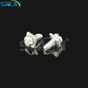
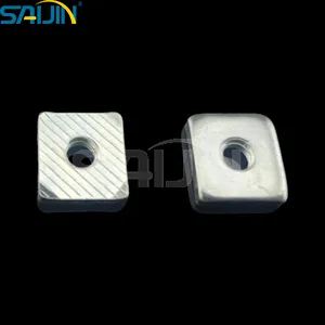
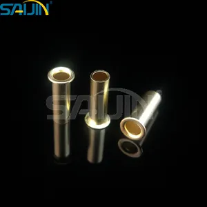
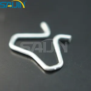
When system reliability depends on welded silver contacts staying within specification for years, the manufacturing precision and quality control behind each Welded Stamping Parts assembly determine field performance. Saijin (Wenzhou Saijin Electrical Alloy Co., Ltd.) manufactures welded stamping parts using automated laser welding and induction brazing processes that achieve ≤5 μm positional accuracy and weld penetration ≥0.3 mm. Every assembly is subject to 100 % automated optical inspection and electrical testing, maintaining a defect rate below 0.1 %. The product line includes silver solder stamping parts electrical moving contact, bridge contacts for thermal overload protectors and motor starters, silver brazed contacts for switches and relays, and AgCdO and AgSnO₂ contacts for high‑load applications. Saijin holds ISO9001:2015, IATF 16949, and meets EU RoHS and REACH requirements. With more than 20 years of experience and an annual production capacity exceeding one billion pieces, Saijin provides application consulting, failure analysis, and technical documentation throughout the product development cycle. Saijin also offers customization of off‑standard sizes, shaped structures, and special performance requirements for customers worldwide.
→ Request a quote from Saijin for the Silver Solder Stamping Parts Electrical Moving Contact — Share your application (relay, contactor, thermal protector), load type (resistive, inductive, capacitive), switching frequency, and required silver alloy (AgNi, AgSnO₂, or custom composition). Their engineering team can recommend the right welded stamping parts configuration and provide sample assemblies for validation testing.