A relay manufacturer in Spain kept rejecting batches of contact terminals because the silver contact button would detach from the copper carrier after 8,000 cycles. The failure was not in the silver alloy—it was in the attachment method. The supplier used a staking process that deformed the carrier around the contact, leaving a mechanical interlock that relaxed under thermal cycling.
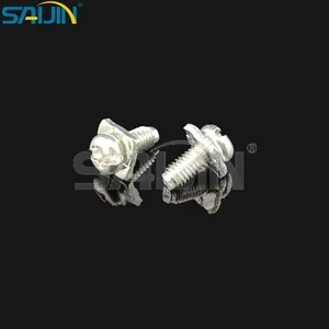
The fix was a welded stamping parts assembly where the silver alloy button is laser‑welded to the copper carrier. The weld penetrates to a depth of ≥0.3mm, creating a metallurgical bond that does not relax. A welded stamping parts assembly from Saijin combines precision progressive die stamping with automated silver alloy welding. The contact resistance is less than 0.5mΩ, the tensile strength exceeds 200N, and the design is optimized for high‑vibration environments such as automotive relays and industrial controllers.
A welded stamping parts system eliminates the two failure modes that plague mechanically attached contacts: loose rivets that spin in their sockets and brazed joints that crack under thermal cycling. The laser welding process heats only the interface between the silver alloy and the copper carrier, so the temper of the stamped spring arm is not affected. The mechanical properties of the base material—hardness, yield strength, and fatigue resistance—remain unchanged after welding. The resulting connector, known as a welding assembling stamping parts electrical connector, is used in applications where vibration would loosen a crimped or staked terminal within months.
Laser welding vs. brazing: why a 0.3mm penetration depth outlasts a 0.1mm brazed joint
A brazed joint uses a filler metal that melts at a lower temperature than the base materials. The filler flows into the gap between the silver contact and the copper carrier by capillary action. The bond strength is limited by the strength of the filler and the quality of the wetting. Brazing also requires the entire assembly to be heated to the melting point of the filler, which can anneal the stamped spring arm, reducing its spring force.
Laser welding fuses the silver alloy and copper carrier directly, without a filler metal. The heat‑affected zone is localized to the weld spot, leaving the surrounding material unaffected. The weld penetration depth is controlled to ≥0.3mm, enough to create a full‑strength joint without burning through the thin silver layer.
| Attachment Method | Bond Type | Typical Tensile Strength | Heat Impact on Base Metal | Failure Mode |
|---|---|---|---|---|
| Staking / riveting | Mechanical | 50‑100N | None | Loose over time |
| Brazing (silver solder) | Metallurgical (filler) | 100‑150N | Anneals spring arm | Filler creep, joint cracking |
| Resistance welding | Metallurgical (direct) | 150‑200N | Localized | Electrode wear |
| Laser welding | Metallurgical (direct) | 200‑300N | Minimal | None within design life |
A welded stamping parts assembly with laser‑welded silver contacts can be heat‑treated after welding if the application requires a specific hardness. For a silver‑tin oxide contact on a beryllium copper spring arm, the entire assembly can be aged to achieve the spring temper without affecting the weld integrity. The weld does not crack during the heat treatment because the bond is continuous and the coefficients of thermal expansion of silver and copper are similar.
Progressive die stamping with in‑process welding: why the contact is welded before the carrier is separated
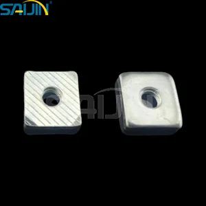
A welding assembling stamping parts electrical connector is produced on a progressive die line where the stamping and welding steps are integrated. The copper strip enters the press, is pierced and blanked to form the carrier shape, and then moves to a welding station where a silver alloy wire or pre‑formed contact is welded onto the carrier. The carrier is then separated from the strip, formed (bent) to its final shape, and plated.
This in‑process welding offers two advantages over post‑stamping welding. First, the carrier is still flat when welded, so the weld electrodes can access the weld site without interference from formed features. Second, the strip provides a common ground for the welding current, ensuring consistent energy delivery to each weld.
The welding process is monitored in real time by a current and displacement sensing system. The weld energy is adjusted automatically if the contact thickness varies. A weld that does not meet the penetration depth spec is rejected immediately, not after final assembly. For a high‑volume automotive relay manufacturer producing 10,000 parts per hour, this real‑time quality control prevents the shipment of connectors with weak welds.
Why the silver alloy composition affects weldability
Silver‑cadmium oxide (AgCdO) has a higher electrical resistance than fine silver, which makes it easier to weld because the resistance at the interface generates more heat. Silver‑tin oxide (AgSnO₂) is more difficult to weld because its resistance is lower and the tin oxide particles can interfere with the weld nugget formation. Saijin's welding parameters are tuned for each alloy. For AgSnO₂, the welding current is increased and the weld time is extended to achieve the same 0.3mm penetration depth as AgCdO. The welding data is stored in the PLC, so changing from AgCdO to AgSnO₂ is a recipe recall, not a re‑qualification.
The standard silver plating thickness on the contact face is ≥3μm (tin‑plated copper alloy base). For harsh environments, a 5μm silver coating is available, doubling the corrosion barrier for coastal or marine applications. The plating is applied after welding, so the weld joint is also plated, preventing galvanic corrosion between the silver alloy and the copper carrier.
The company’s quality management system is certified to IATF 16949 (automotive), ISO 9001:2015, and ISO 14001, with RoHS and REACH compliance documentation included with each shipment.
200N tensile strength and <0.5mΩ contact resistance: why the numbers matter for a 60A battery disconnect
A welded stamping parts assembly used in a battery disconnect switch must carry 60A of continuous current without overheating. The contact resistance determines the power dissipated as heat: P = I²R. At 60A, a 0.5mΩ contact dissipates 1.8W; a 1.0mΩ contact dissipates 3.6W—double the heat. In a sealed enclosure, that extra 1.8W can raise the internal temperature by 10‑15°C, accelerating the aging of adjacent components.
The tensile strength of the weld (200N) ensures that the contact does not detach if the switch experiences a shock load. A 10G shock on a 5‑gram contact generates 0.5N of force—far below the 200N rating. The safety margin is large enough to absorb variations in the welding process.
For a relay with a moving contact arm that flexes 0.5mm during operation, the welded joint is subjected to cyclical bending stress. A brazed joint may develop fatigue cracks after 100,000 cycles because the filler metal is softer than the base materials. A laser‑welded joint has a fatigue strength close to that of the base material, so the failure mode shifts from joint fracture to spring arm fatigue—a predictable, end‑of‑life event rather than a premature failure.
The mechanical properties of the welded assembly include a 40% improvement in impact resistance compared to staked or riveted designs. For a starter solenoid mounted on an engine block, the welded contact will not loosen even after years of vibration. The impact resistance is measured by dropping a weight onto the contact assembly and measuring the force required to separate the weld. The test passes if the carrier yields before the weld breaks.
Design support for non‑standard shapes: why a custom stamped part costs less than a second‑source alternative
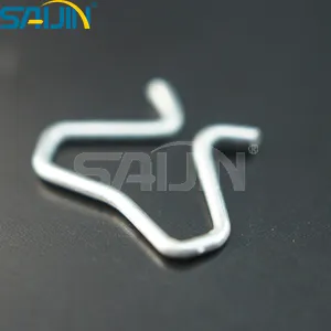
A welding assembling stamping parts electrical connector is not limited to standard terminal shapes. Saijin's design team provides support for non‑standard sizes, shaped structures, and special functional requirements. The tooling for a progressive die is designed around the customer’s 3D CAD model. The welding station is then integrated into the die.
For a customer who needs a terminal with a 90° bend, a weld pad on the side of the carrier, and a retention feature to lock the connector into a housing, Saijin can produce the part as a single stamping. A second‑source supplier might require two separate parts (carrier and contact) and a secondary assembly step. The single‑part approach reduces assembly labor and eliminates the risk of misaligning the contact during assembly.
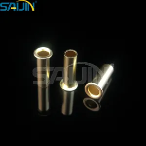
The company maintains an inventory of common copper alloys (C1100, C194, brass, phosphor bronze) and silver alloy wire (AgSnO₂, AgNi, AgCdO). 48‑hour rapid prototyping is available for urgent new designs. The prototype uses the same welding parameters and material specifications as the production order, so the customer can validate the contact resistance and pull force before committing to high‑volume tooling.
The 48‑hour service requires an in‑house toolroom with CNC machining centers and a wire EDM for electrode fabrication. The design team uses finite element analysis to simulate the stamping process and the weld cooling rate. For a customer who has had reliability issues with a brazed contact, Saijin can recommend a weld‑optimized silver alloy that may be more weldable than the customer’s current material.
Why the weld electrode material matters
The welding electrodes contact the silver alloy and the copper carrier to deliver the welding current. Electrodes made of tungsten‑copper alloy have a longer service life than pure copper electrodes, but they also have a higher contact resistance, which reduces the current delivered to the weld. Molybdenum‑tungsten electrodes are used for welding silver‑tin oxide because of the higher temperatures required. The electrode wear is monitored by counting welds. After a preset number (typically 50,000‑100,000), the electrode is replaced, and the machine re‑calibrates the welding energy.
IATF 16949 and the audit trail: why an automotive relay supplier needs terminal traceability from coil to carton
A welded stamping parts assembly that goes into an automotive door latch or a battery management system must be traceable from the finished assembly back to the batch of raw material. If a field failure occurs, the supplier must identify which shift produced the faulty batch and which coil of copper alloy supplied the material.
Saijin’s IATF 16949 certification for its stamped parts line mandates a closed‑loop quality system. Each coil of copper or brass is logged with its mill certificate. The stamping press logs the batch number, the tooling ID, and the operator. The welding machine logs the welding current, weld time, and displacement data for each part. The AOI system records the measurement data for every part in the batch. The finished reels are labeled with a traceable QR code. An audit trail that would take an uncertified supplier days to assemble is available from Saijin’s production database in minutes.
The ISO 9001:2015 certification assures stable quality, with regular customer audits and internal audits to maintain certification. The company has been awarded the Zhejiang Province scientific and technological enterprise.
The material certification package includes RoHS, REACH compliance reports, and material composition analysis. For a relay manufacturer exporting to Europe, these certifications are not optional; they are legal requirements for market access.
The company supplies its welded stamping parts to customers in the automotive, industrial control, consumer electronics, and medical device industries. Annual production capacity exceeds 100 million parts, with tooling designed for a minimum die life of 1,000,000 strokes. Wear parts (punches, dies, welding electrodes) are replaced on a preventive schedule, not when they fail.
How Saijin’s welded stamping parts fit into a switch or relay assembly line
Saijin Electric (Wenzhou Saijin Electrical Alloy Co., Ltd.) has manufactured stamped parts and silver alloy contacts for switches, relays, circuit breakers, and connectors. The welded stamping parts line includes custom tooling for customer‑supplied drawings, progressive die stamping with in‑process laser welding, silver alloy contacts (AgSnO₂, AgNi, AgCdO, AgZnO), copper alloy carriers (C1100, C194, brass, phosphor bronze), ≥0.3mm weld penetration depth, <0.5mΩ contact resistance, 200N minimum tensile strength, ≥3μm silver plating (5μm optional), IATF 16949 and ISO 9001:2015 certification, and RoHS/REACH compliance with full material certification.
The delivery for standard parts is 7‑15 days; rapid prototyping is available within 48 hours for urgent requests. The tooling is designed for a minimum die life of 1,000,000 strokes, with wear parts that can be replaced without scrapping the entire die block.
A welded stamping parts assembly that does not loosen under vibration, survives 200N pull force, and maintains <0.5mΩ resistance for the life of the product replaces staked contacts and brazed assemblies in high‑reliability applications. For a relay manufacturer who has experienced field failures due to loose contacts, Saijin’s laser‑welded, progressive‑die stamped electrical connectors deliver the mechanical integrity and traceability that IATF 16949 demands.
【Request a quote from Saijin Electric】
Send Saijin your terminal drawing, silver alloy type (AgSnO₂, AgNi, or AgCdO), and estimated annual volume to receive a welded stamping parts quotation with a full IATF 16949 certification package and a sample weld cross‑section image.